

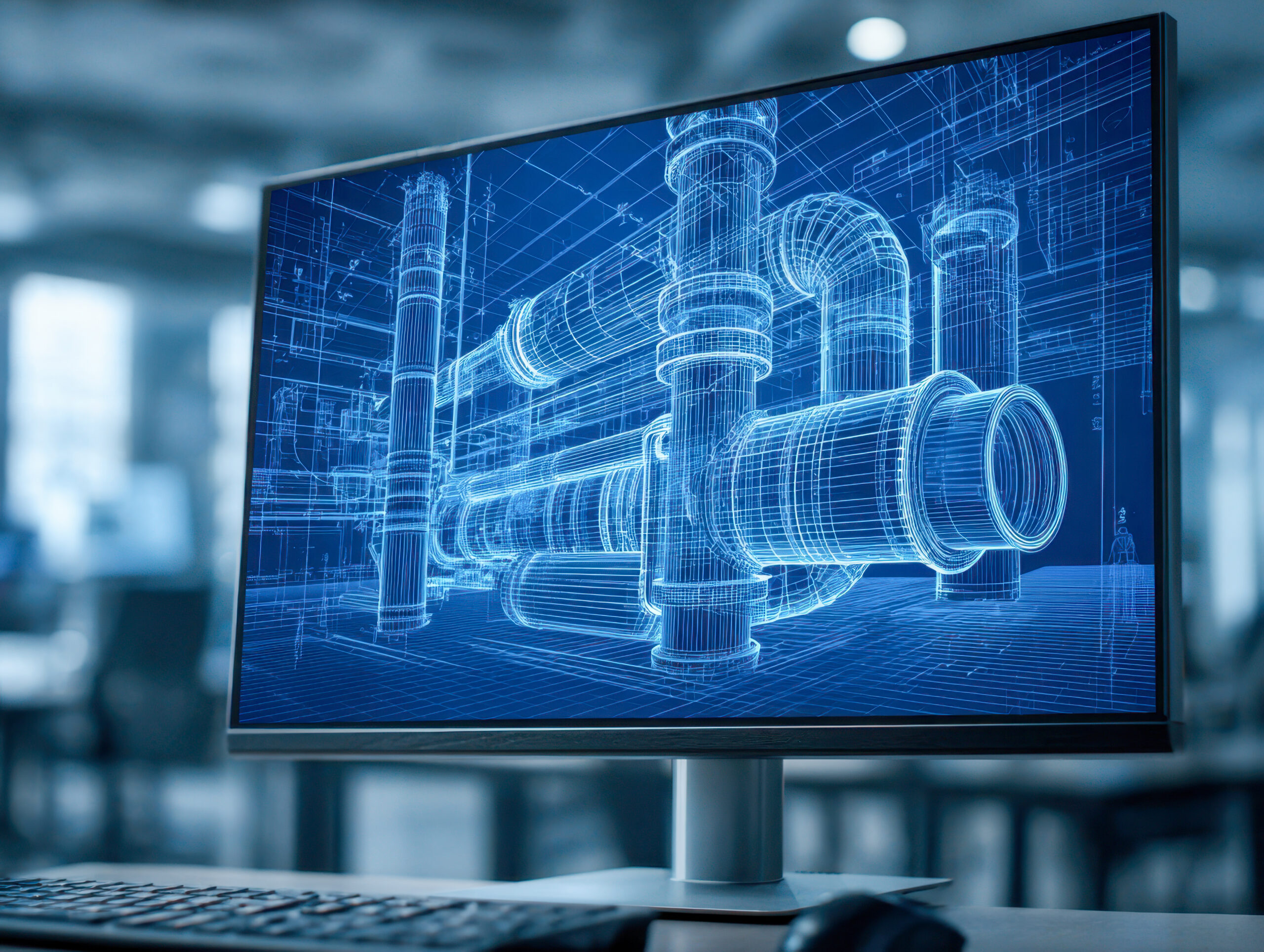
MEPFP BIM Modeling Services provide a structured digital representation of the mechanical, electrical, plumbing, and fire protection systems within a building or facility. Instead of representing building services only through separate 2D drawings, BIM brings these systems into a coordinated three-dimensional environment where their geometry and associated information can be reviewed together. This becomes particularly important on complex projects because ducts, pipes, cable trays, electrical equipment, sprinkler systems, mechanical equipment, ceilings, structural beams, and architectural elements often compete for the same physical space. A well-developed MEPFP BIM model gives project teams a better way to visualize, coordinate, document, and manage these systems. For new construction, the model can support design coordination and construction planning. For existing buildings, 3D laser scanning and Scan to BIM can be used to capture the actual MEP installation and convert the resulting point cloud into an as-built Revit model. This reality-based approach can be extremely useful for renovation, retrofit, facility upgrades, plant modifications, tenant fit-outs, and asset management. For VB Terrascan, MEPFP BIM modeling fits naturally within a broader workflow of Scan → Point Cloud → BIM → Digital Twin, helping clients move from physical site conditions to structured digital information.
What Are MEPFP BIM Modeling Services?
MEPFP BIM Modeling Services involve creating intelligent BIM models for mechanical, electrical, plumbing, and fire protection systems. The model may represent HVAC equipment, air-handling units, chillers, pumps, ducts, pipes, electrical panels, cable trays, conduits, lighting systems, plumbing fixtures, drainage systems, fire pumps, sprinkler networks, fire hydrants, and other building-services components depending on the project requirements.
Unlike basic 3D drafting, BIM modeling connects geometry with information. A mechanical duct, for example, can be represented with dimensions, system information, material data, elevation, connections, and other parameters. Similarly, a pump can be represented as an equipment element with relevant information associated with the model component.
The purpose is not simply to create a visually impressive 3D model. The model should support a specific project objective such as design coordination, construction, clash detection, quantity-related workflows, fabrication, as-built documentation, or facility management.
For existing facilities, the source information may include drawings, photographs, surveys, and laser-scanned point clouds. The modeling team interprets this information and creates the required BIM elements according to the project’s standards and Level of Development.
What Does MEPFP Stand For?
MEPFP generally refers to:
- M — Mechanical
- E — Electrical
- P — Plumbing
- FP — Fire Protection
The exact scope can vary between projects. Some organizations use MEPF to refer to Mechanical, Electrical, Plumbing, and Fire Fighting, while others use MEPFP to explicitly identify fire protection. Regardless of terminology, the objective is the same: creating a coordinated digital representation of critical building-services systems.
Why MEPFP BIM Modeling Is Important
Modern buildings contain increasingly complicated building-services infrastructure. A hospital may contain HVAC systems, medical gas services, electrical infrastructure, plumbing, fire protection, specialist equipment, and extensive ceiling services. An industrial facility can have process piping, compressed air, ventilation, electrical distribution, fire protection, and equipment connections. A commercial building may contain chilled-water systems, air-conditioning ducts, electrical systems, plumbing, drainage, and sprinkler networks.
Trying to coordinate all these systems through disconnected drawings can become difficult.
BIM provides a common digital environment where these systems can be reviewed together. This allows project teams to identify potential spatial conflicts before installation. For example, a large duct may conflict with a structural beam, a sprinkler pipe may interfere with lighting, or a cable tray may occupy the same zone as another service.
Finding these issues during design is generally much easier than discovering them after construction has started.
MEPFP BIM therefore acts like a digital rehearsal of the building-services installation. Teams can review the proposed arrangement before materials arrive on site.
What Is Included in an MEPFP BIM Model?
The content of an MEPFP BIM model depends on the project scope and required Level of Development. Typical elements can include:
| Discipline | Typical BIM Elements |
| Mechanical | HVAC equipment, ducts, AHUs, FCUs, chillers, pumps, diffusers |
| Electrical | Panels, cable trays, conduits, lighting, electrical equipment |
| Plumbing | Water pipes, drainage, sanitary fixtures, pumps |
| Fire Protection | Sprinklers, fire pipes, fire pumps, hydrants, valves |
| Coordination | Openings, sleeves, equipment clearances, service zones |
| Documentation | Plans, sections, elevations, schedules, views |
The project team should define exactly which systems and components need to be modeled. A facility-management model may require different information from a construction coordination model.
This is why experienced MEPFP BIM modeling companies normally establish the BIM requirements before production begins.
Mechanical BIM Modeling
Mechanical BIM modeling focuses primarily on HVAC and other mechanical systems. Depending on the project, this may include air-handling units, fan-coil units, chillers, pumps, cooling towers, ventilation equipment, ductwork, dampers, diffusers, grilles, valves, mechanical rooms, and associated components.
A coordinated mechanical model helps engineers and contractors understand how systems occupy the building. Duct routing can be reviewed against structural beams, ceilings, electrical systems, plumbing, and fire protection.
For large buildings, this coordination can be extremely important. Mechanical systems often require significant ceiling and plant-room space, and routing changes can affect multiple disciplines.
A properly developed mechanical BIM model can therefore support HVAC coordination, clash detection, documentation, installation planning, and as-built records.
For existing facilities, laser scanning can add another level of confidence by capturing the actual location and geometry of mechanical equipment and ductwork.
Electrical BIM Modeling
Electrical BIM modeling represents electrical infrastructure in a structured digital environment. Depending on project requirements, it can include electrical panels, switchboards, cable trays, conduits, lighting fixtures, equipment connections, electrical rooms, and other components.
Electrical services frequently compete for ceiling and service-space real estate with mechanical, plumbing, and fire-protection systems. A coordinated BIM model can help identify conflicts and support more efficient routing.
Electrical BIM can also support documentation and coordination during construction. Rather than reviewing electrical drawings independently, project teams can examine electrical infrastructure in relation to architectural and structural elements.
For industrial and commercial facilities, accurate as-built electrical BIM can also be useful when planning future modifications, equipment installations, expansions, or maintenance work.
Plumbing BIM Modeling
Plumbing BIM modeling covers domestic water, drainage, sanitary systems, stormwater, pumps, fixtures, valves, and related piping depending on the project’s requirements.
Plumbing systems can become particularly challenging in high-rise buildings because vertical risers, horizontal distribution, drainage slopes, structural penetrations, and ceiling coordination all need to work together.
BIM provides a way to visualize these relationships before installation. Pipes can be modeled at their intended elevations and coordinated with beams, slabs, ceilings, ducts, cable trays, and sprinkler systems.
For renovation projects, an as-built plumbing model can provide a useful digital record of existing services. This can help project teams understand existing routes before introducing new systems.
Fire Protection BIM Modeling
Fire protection is a critical building service, and BIM can help coordinate its physical installation with the rest of the facility.
A Fire Protection BIM Model can represent sprinkler pipes, sprinkler heads, fire pumps, valves, hydrants, hose reels, fire-service piping, equipment rooms, and other components according to project requirements.
Fire-protection services frequently share ceiling space with HVAC ducts, electrical systems, lighting, and plumbing. Coordination is therefore essential.
An accurate BIM environment can help teams identify spatial conflicts and review system routing. For existing facilities, Scan to BIM can provide a digital reference for documenting installed fire-protection infrastructure.
The BIM model should always follow the applicable project specifications, fire codes, engineering design, and approved documentation. Modeling is a representation of the design or installed condition; it does not replace professional fire-protection engineering.
Revit MEPFP Modeling Services
Autodesk Revit is commonly used for BIM-based building-services modeling because it supports multidisciplinary coordination and information-rich building elements.
A Revit MEPFP model can bring mechanical, electrical, plumbing, and fire-protection systems into a coordinated project environment. Teams can create views, sections, schedules, and other documentation from the model while maintaining relationships between components.
The advantage becomes especially apparent when project changes occur. If a duct route changes, associated views can reflect that change because they are derived from the model.
For BIM outsourcing, clients should specify the required Revit version, project template, family standards, coordinates, naming conventions, modeling scope, and deliverables before production begins.
These details can make a major difference to the usability of the final model.
MEPFP Scan to BIM
MEPFP Scan to BIM combines 3D laser scanning with BIM modeling to document existing building-services systems.
The workflow generally begins with scanning the physical environment. The captured data is processed and registered into a point cloud. BIM specialists then use that point cloud as a reference for modeling the relevant MEPFP elements.
This is especially useful when existing drawings are unavailable or unreliable.
Imagine an industrial facility that has undergone ten years of modifications. The original HVAC drawings may show where the ducts were supposed to be installed, while the physical building contains additional ducts, relocated equipment, new cable trays, modified pipes, and other changes.
A laser scan can capture the current environment.
The BIM model can then be developed from that captured information.
VB Terrascan positions its reality-capture workflow around Scan → Point Cloud → BIM → Digital Twin, making this approach relevant for existing MEPFP documentation. (vbterrascan.com)
Point Cloud to MEP BIM Modeling
A point cloud to MEP BIM workflow transforms captured spatial information into structured building-services elements.
A point cloud contains millions of points representing surfaces and objects captured during scanning. The BIM modeler interprets these points and identifies relevant systems.
For example, the modeler may identify a cylindrical cluster of points as a pipe, determine its route and diameter, and represent it as the appropriate BIM pipe element. Similarly, ducts, equipment, structural components, and other services can be modeled according to the agreed scope.
The point cloud provides measured spatial evidence, while the BIM model provides structured information.
This distinction is important because converting a point cloud into BIM is not simply an automatic conversion process. Professional interpretation is required to determine what should be modeled, how it should be represented, and what information should be attached to each element.
MEPFP As-Built BIM Modeling
MEPFP As-Built BIM Modeling creates a digital representation of building-services systems as they actually exist in the facility.
This can be valuable because construction changes are common. Equipment may be relocated, pipes may be rerouted, ducts may be modified, electrical infrastructure may be expanded, and additional fire-protection systems may be installed.
The final building may therefore differ from the original design.
An as-built BIM model aims to document the current condition rather than the original design intent.
When combined with 3D laser scanning, the workflow can provide a stronger information foundation for the model. The resulting BIM can support renovation, maintenance planning, facility management, future design, and digital-twin development.
For building owners, this can be particularly valuable because accurate MEP documentation can reduce uncertainty when future work is planned.
MEP Coordination and Clash Detection
One of the most important applications of MEPFP BIM is clash detection.
Consider a ceiling void containing a large HVAC duct, multiple sprinkler pipes, electrical cable trays, plumbing lines, and lighting fixtures. There is only a limited amount of physical space.
Without coordination, these systems can easily conflict.
BIM coordination allows the team to review the systems together and identify potential clashes. The design can then be adjusted before installation.
Typical MEPFP clashes include:
- Duct versus structural beam
- Pipe versus duct
- Cable tray versus pipe
- Sprinkler versus lighting
- Equipment versus architectural clearance
- Service route versus ceiling
- Pipe or duct versus structural opening
The objective is not simply to produce a clash report. The real value comes from resolving the issue and creating a coordinated design that can be constructed.
Benefits of MEPFP BIM Modeling
MEPFP BIM modeling can provide significant benefits across design, construction, and facility management.
Better Coordination
The biggest benefit is often interdisciplinary coordination. Multiple building-services systems can be reviewed in one environment rather than separately.
Reduced Rework
Identifying conflicts earlier can reduce the likelihood of expensive modifications during construction.
Improved Visualization
A three-dimensional model makes complicated service routes easier to understand, especially in plant rooms and congested ceiling spaces.
Better Documentation
Model-based views, schedules, and sections can provide a more coordinated documentation workflow.
Faster Design Changes
Because model elements are connected, changes can be managed more systematically than in disconnected drawing workflows.
Better As-Built Information
Scan-to-BIM workflows can create digital documentation of existing MEPFP installations.
Digital Twin Readiness
A structured MEPFP model can become part of a broader digital representation of a facility when integrated with appropriate asset and operational information.
MEPFP BIM Workflow
A professional MEPFP BIM project should follow a defined workflow.
Step 1: Project Requirement Analysis
The BIM team reviews the client’s objectives, available information, required disciplines, model scope, LOD/LOI requirements, coordinates, software version, and deliverables.
Step 2: Source Data Collection
Information may include drawings, CAD files, PDFs, specifications, photographs, surveys, or point clouds.
Step 3: Laser Scanning Where Required
For existing facilities, 3D laser scanning can capture the current physical environment.
Step 4: Point Cloud Processing
The captured scans are registered and processed into a usable point-cloud dataset.
Step 5: BIM Modeling
Relevant mechanical, electrical, plumbing, and fire-protection elements are modeled in Revit according to project standards.
Step 6: Coordination
The MEPFP model is coordinated with architectural and structural information.
Step 7: Clash Detection
Potential conflicts are identified and reviewed.
Step 8: Quality Assurance
The model is checked against source information and project requirements.
Step 9: Final Delivery
The final Revit model and other agreed deliverables are provided to the client.
This structured process creates a clear connection between the physical facility, captured data, BIM model, and final project deliverables.
MEPFP BIM for Existing Buildings
Existing buildings are often where MEPFP BIM delivers some of its greatest value.
Original MEP drawings may be missing or outdated. Even when drawings exist, they may not reflect years of modifications.
This creates a problem for anyone planning renovation.
A design team needs to know where existing services are before introducing new systems.
Reality capture can provide that missing information.
Laser scanning can document accessible physical surfaces and service locations. The resulting point cloud becomes a reference for creating an as-built BIM model.
For a large commercial building, this might mean documenting HVAC ducts, electrical trays, plumbing systems, and fire protection before a major refurbishment.
For an industrial facility, the model may also include process-related piping, equipment, platforms, and structural elements depending on the project scope.
VB Terrascan’s reality-capture services are designed around these types of workflows, connecting 3D scanning and point-cloud information with BIM and digital-twin applications. (vbterrascan.com)
Industries That Need MEPFP BIM Services
MEPFP BIM services are relevant to almost any complex facility.
Commercial Buildings
Office towers, shopping centers, mixed-use developments, and commercial properties often have dense MEP systems requiring coordination.
Healthcare
Hospitals and healthcare facilities contain highly complex mechanical, electrical, plumbing, and fire-protection systems.
Industrial Facilities
Factories and plants often contain complicated piping, ventilation, electrical distribution, fire protection, and equipment services.
Data Centers
Data centers have demanding mechanical and electrical requirements where spatial coordination and accurate documentation are critical.
Airports
Airport facilities combine large architectural environments with extensive MEP infrastructure.
Hotels
Hotels contain HVAC, plumbing, electrical, fire protection, kitchens, laundry systems, and other building services.
Warehouses and Logistics Parks
Large warehouses require coordinated services for lighting, HVAC, fire protection, electrical distribution, and specialized equipment.
Heritage Buildings
Historic buildings may require careful documentation before restoration or adaptive reuse.
VB Terrascan identifies sectors including airports, commercial spaces, industrial parks, healthcare, logistics parks, heritage, hospitality, oil and gas, power infrastructure, water infrastructure, and sports arenas within its broader reality-capture offering. (vbterrascan.com)
How to Choose an MEPFP BIM Company
Choosing an MEPFP BIM provider should start with the project’s requirements rather than price alone.
First, determine whether the company has experience with the type of facility being modeled. MEP coordination for an office building is very different from modeling an industrial plant.
Second, ask whether the provider can work from point clouds and laser-scanning data if the project involves an existing building.
Third, confirm the software environment, Revit version, BIM standards, LOD requirements, file formats, coordinates, and quality-control process.
Fourth, ask for relevant examples. A provider experienced in architectural BIM may not necessarily have deep MEPFP expertise.
Finally, establish how the model will be used after delivery. If the objective is facility management or digital-twin development, the model may require different information than a model intended only for construction coordination.
A good BIM provider should ask these questions before production begins.
Why Choose VB Terrascan for MEPFP BIM?
VB Terrascan combines 3D laser scanning, point-cloud processing, Scan to BIM, Revit BIM modeling, and digital-twin workflows. This integrated capability is particularly useful when the project involves existing buildings where reliable MEPFP documentation needs to be developed from physical conditions. (vbterrascan.com)
Instead of treating scanning and BIM as unrelated services, the workflow connects the two.
Scan → Point Cloud → BIM → Digital Twin
This provides a practical pathway from the physical facility to a structured digital representation.
VB Terrascan’s Scan to PCD service also describes high-precision 3D laser scanning and point-cloud outputs for BIM, CAD, and digital-twin workflows. (vbterrascan.com)
For MEPFP projects, this can help clients create reliable digital documentation for renovation, coordination, expansion, asset management, and future facility development.
The focus should always remain on the client’s intended use. A successful MEPFP BIM project is not defined by how complicated the model looks; it is defined by whether the model contains the right information, at the right level of detail, in a format that the project team can actually use.
MEPFP BIM Modeling FAQs
What are MEPFP BIM Modeling Services?
MEPFP BIM Modeling Services involve creating digital BIM models of Mechanical, Electrical, Plumbing, and Fire Protection systems. These models can support design coordination, construction, clash detection, documentation, as-built modeling, and facility management.
What software is commonly used for MEPFP BIM modeling?
Autodesk Revit is widely used for MEP BIM modeling. Depending on project requirements, the workflow can also involve point-cloud processing, coordination, analysis, fabrication, and other specialist platforms.
Can MEPFP BIM models be created from point clouds?
Yes. Point cloud to MEP BIM is a common Scan to BIM workflow for existing buildings. Laser scanning captures the physical environment, and BIM specialists use the resulting point cloud as a reference for modeling existing systems.
What is MEPFP Scan to BIM?
MEPFP Scan to BIM combines 3D laser scanning and BIM modeling to create digital representations of existing mechanical, electrical, plumbing, and fire-protection systems.
How much do MEPFP BIM Modeling Services cost?
Pricing depends on building size, system complexity, number of disciplines, source-data quality, scanning requirements, required LOD, project location, deliverables, and project schedule. A detailed project assessment is normally required before providing an accurate quotation.
Conclusion
MEPFP BIM Modeling Services provide a structured way to digitally represent and coordinate mechanical, electrical, plumbing, and fire-protection systems. By bringing these systems into a common BIM environment, project teams can visualize complex installations, identify potential clashes, coordinate routes, produce documentation, and improve the information available for construction and facility management.
For existing buildings, the combination becomes even more powerful when 3D laser scanning and Scan to BIM are introduced. Instead of depending entirely on outdated drawings, teams can capture current site conditions, process the information into point clouds, and use that data to develop an as-built MEPFP BIM model.
For complex facilities, this can create a valuable digital foundation for renovation, retrofit, expansion, maintenance planning, coordination, and digital-twin development.
For VB Terrascan, the combination of 3D Laser Scanning → Point Cloud → MEPFP BIM → Digital Twin creates a strong service proposition for organizations that need accurate digital documentation of existing facilities.
The future of building-services documentation is not simply about producing more drawings. It is about creating accurate, coordinated, information-rich digital assets that remain useful long after a project reaches completion.
MEPFP BIM Modeling Services
VB Terrascan provides MEPFP BIM Modeling Services for Mechanical, Electrical, Plumbing, and Fire Protection systems using Revit, point clouds, and reality-capture data. Our BIM workflows help clients create accurate, coordinated digital representations of complex building-services infrastructure.
For existing facilities, we combine 3D laser scanning, point-cloud processing, Scan to BIM, and Revit MEPFP modeling to develop as-built BIM models that reflect observed site conditions. These models can support renovation, retrofit, facility upgrades, clash detection, construction coordination, asset documentation, and digital-twin initiatives.
Our MEPFP BIM capabilities can cover HVAC systems, mechanical equipment, electrical systems, cable trays, plumbing networks, drainage, fire-protection systems, equipment rooms, and other MEP services, depending on project requirements.
From Scan → Point Cloud → BIM → Digital Twin, VB Terrascan helps transform complex physical facilities into structured digital assets that project teams can use for better coordination and decision-making.
